In my previous blog post, I started talking about the why of my weird passion for road networks. I mostly tried to express how infrastructure can be a form of art and show the intricacies and details that often get overlooked in Games.
I intentionally kept the technicalities out, which was mostly fine, but a lot of folks were like: “Ok. Great tale, but show us how you do it.” Which is totally understandable. I guess that’s a fair question for a curious audience. Let’s dive into the foundation block of every software:
The data model layer
Something that I often see software people spend way too little time on is the data representation of their software. I consider the data model so fundamental to any software that can be the make or break of it.
I’ve seen this approach countless times: “Let me just put something there so I can progress with my system, and I will refactor and add stuff along the way”. I like to think of the data model as the blueprints of a construction project. You really need to think it through before starting.You just can’t change your plan mid-construction without making serious compromises.
My goal was to come up with a data model that can literally represent any road infrastructure I can see in real life. The question now is: how can you represent roads as data? Let’s start with the simplest one
The Grid
The most primitive way of representing roads is, of course, the grid. I am mentioning this just for completeness, as it’s clear to anyone that it’s more of a stylized representation than a realistic one.
In grid-based road systems, each cell is either empty, a road, or an intersection. Some games go a step further and add different angles so you can have diagonal roads or elevation, but the underlying representation is the same: each tile stores how the road segment should look.
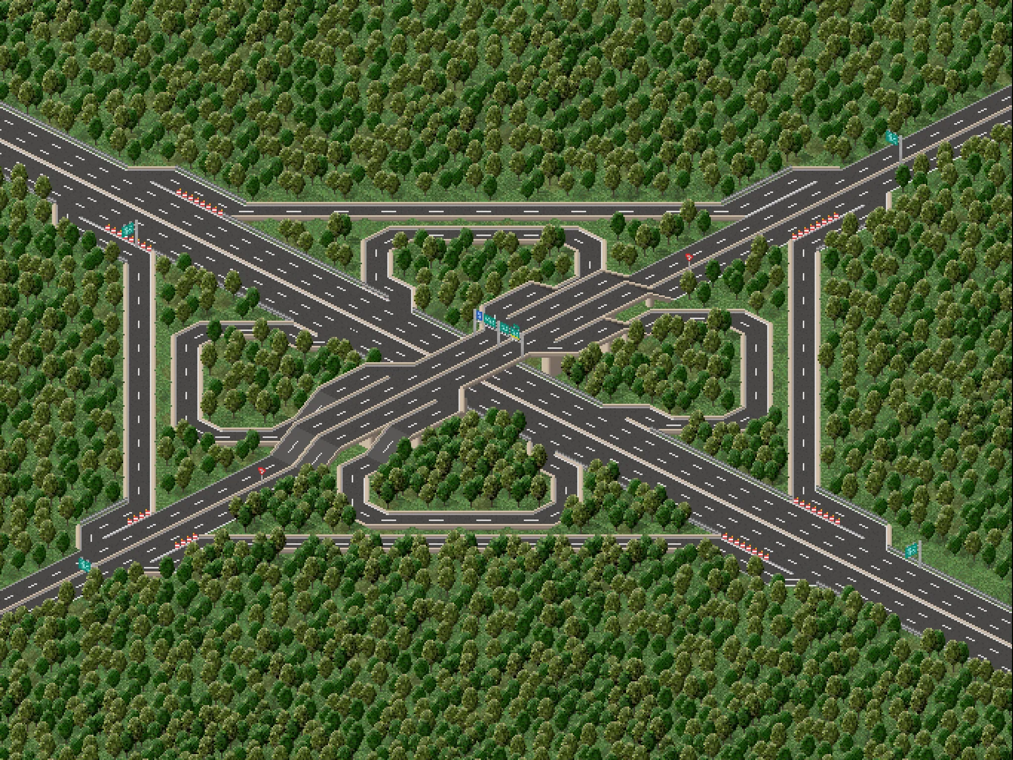
I mean, look at this cloverleaf interchange in TheoTown, I have to admit this is cool.
Node Based Representation
We’re now getting to the first data representation I ever even considered: the node-based approach. The first time I played a game that procedurally drew road geometry using a node-based representation was Cities: Skylines 1. Back then, I was amazed by the freedom and customization this model enabled.
If you think about the best way to store road data, this solution might be obvious. Roads are the go-to explanation for students when they are taught graphs in Computer Science class. The idea is simple: edges are the road segments, and nodes are intersections. Why would you ever need more?
The data for this model is straightforward: each node has a center coordinate and a list of incoming edges. Edges are then responsible for holding information about the road width, lane count, and other road segment information. New nodes are created whenever two road segments intersect. The engine then generates the geometry by connecting lanes from each incoming segment to lanes of other segments.
The Hidden Problem: Lanes
At first glance, this works well. And that’s true for most scenarios, like wide-angles city-level intersections. The problem with this approach becomes more apparent in extreme scenarios, such as highway splits or merges.
Consider this example of a three-lane highway where the outer lane turns into an exit ramp in CS1.
In reality, left lanes should have a clear straight continuation, while only the outer right one should split. If the road is represented just by its centerline, this information is lost. The system simply sees two segments meeting in a node and must infer how lanes connect. The information about which lane should continue, merge, or diverge is missing because that intent was never encoded in the data representation in the first place.
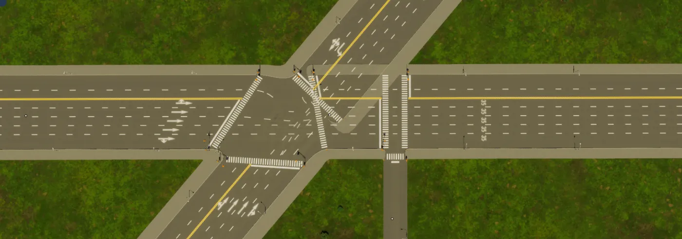
Moreover, there is also a geometric limitation. For lanes to blend smoothly at intersections, this approach requires the connected segments to have a reasonable offset from the node center. Because of this, two intersections cannot be placed arbitrarily close to each other. In other words, between nodes there must be a segment of minimum length. Here is how geometry starts to degenerate when you try to connect a smaller road near a larger intersection node in CS2:
The Workarounds
The pitfalls I’ve just mentioned are fixed by some very talented community developers in CS1. For example, the Node Controller mod allows fine-grained control over a node’s properties, letting you manually adjust how road segments connect and align. This was honestly a game-changer for me back when I played the game. Essentially, this mod allowed you to modify a road’s centerline so its edge aligned with the edge of another road segment. It fixed the intersection but ruined the alignment down the road, literally.
When Cities: Skylines II launched, the developers addressed many of these shortcomings by layering smarter tools on top of that same core node representation. They introduced the ability to align new segments directly to existing lanes, allowing for much more realistic highways. However, despite these impressive quality-of-life improvements, the underlying node-based logic remains, and you can still see its limitations in certain edge cases:
The Missing Link
After experimenting with several approaches, it was clear to me: the problem was not geometry but information. The center point of a node and the edges it connects to are not enough information to describe a road network that accounts for lane continuity or complex scenarios.
I love architecture, especially urban planning. I sometimes find myself, for no apparent reason, browsing and inspecting plans for new urban developments submitted for approval in the city I live in. While looking over those, I noticed they often include diagrams of the road’s cross-section.
They look something like this and are called road profiles.
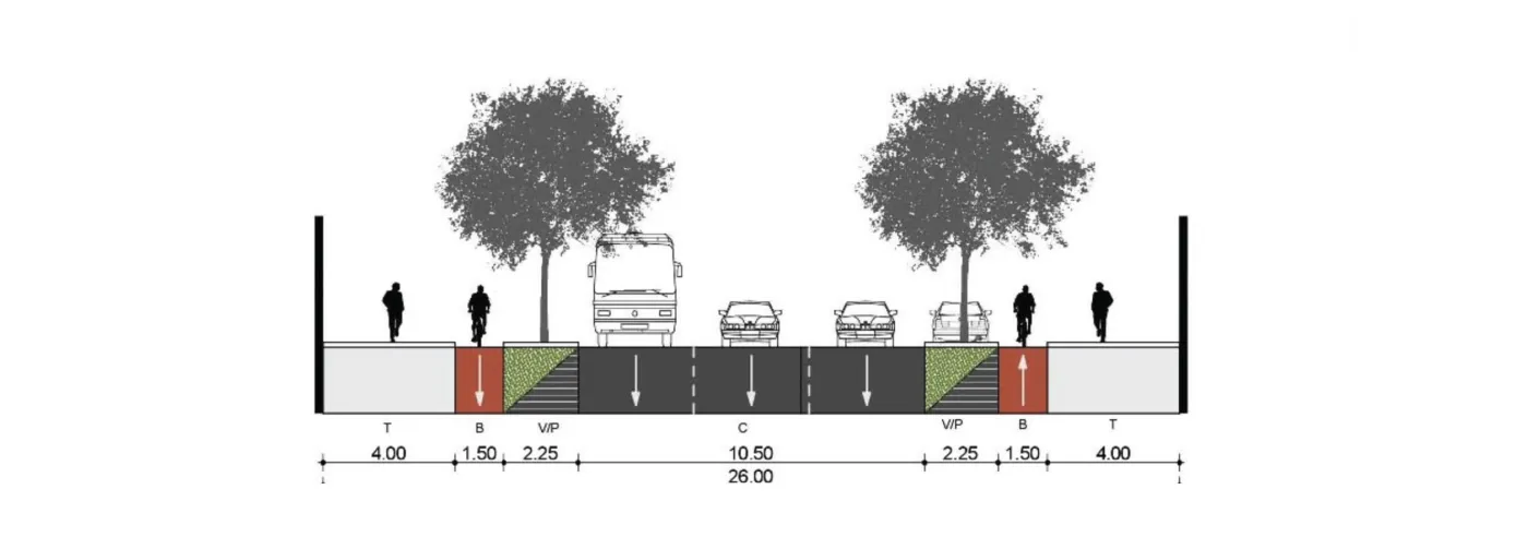
And then it clicked for me. What if, instead of relying on nodes with center points as the source of truth, we make information about the lanes themselves fixed in space? If you explicitly define where each lane should be at each end of a road segment, there is no more room for ambiguity about how those should connect when establishing intersections.
Profiles
Back when I said the road system I am working on isn’t using nodes, I wasn’t entirely accurate. Actually, this system is using nodes, but in an apparent counterintuitive way.
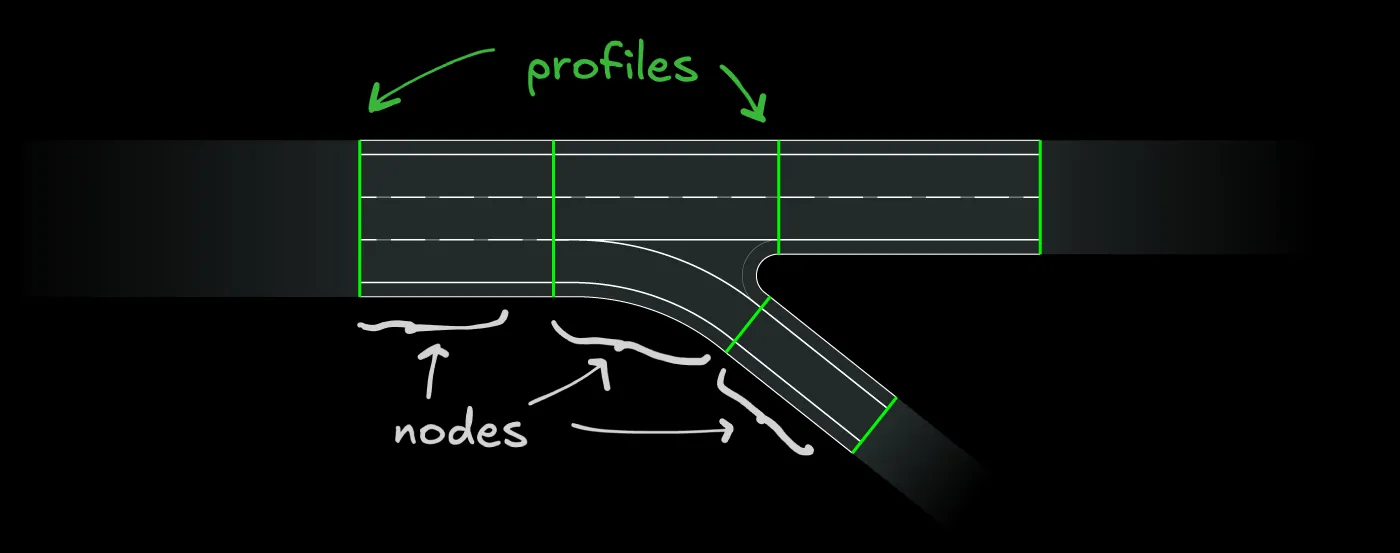
Instead of a node being a physical intersection and an edge being a physical road segment, think of it this way: The physical pieces (segments and intersections) are all nodes. They are stitched together by the edges, which are just some 0-width lines defining the cross section of the road at that specific point. These profiles are abstract representations that render to nothing visually and exist solely to define the road network and store lane data.
To sum up, the mapping goes from:
Nodes = intersections
Edges = roads segments
to
Nodes = all physical pieces (segments and intersections)
Edges = imaginary cross-section lines.
Instead of storing a road as a centerline with some width between two roads, this system stores profiles at connection points. Each profile embeds all the information about the cross-section of a road at that connection point: number of lanes, lane widths, lane types (car, median, sidewalk, bike lane, etc.)
When building an intersection by connecting different profiles, the lane continuity is intentional. Intersections and road segments are generated by establishing smooth transitions between profiles.
Here is a visual representation of this:
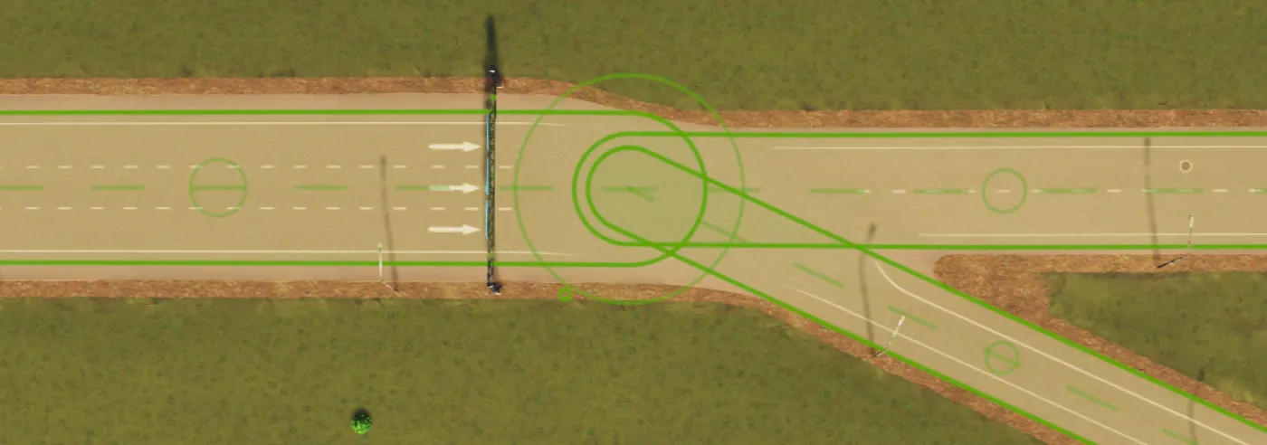
Encoding this data for each profile allows modeling any complex road infrastructure. Here is an overlay of this model over a real-world turbo roundabout.
An Elegant Solution
One might now question: why do you need such a counterintuitive representation when the node-based approach can work with a bit of extra logic? The reason is elegance. I like to think of a solution as elegant when it works without any special handling in all of its possible cases.
For the game devs reading this, picture the difference between Euler angles and quaternions. Both express the rotation of an object. Euler angles work most of the time until they break at a specific edge case (the gimbal lock), while Quaternions are very counterintuitive but offer a universally robust, elegant solution.
Reinventing The Wheel?
I felt quite proud when I finally arrived at this solution, just for a few folks to instantly point out that this problem has already been solved by the automotive industry with the standard ASAM OpenDrive. It’s a much more complex system, but conceptually quite similar, in the sense that lane structure is explicit rather than inferred from a centerline. Inside an intersection, every turning movement is represented by a separate connecting road. My discovery of this existing system humbled me a little, but in the end, I was still happy that I had gotten on the right track on my own. I bet that, with a bit of work, those data models can map 1-to-1 in a lossless manner.
I am planning to get into the actual math I use to interpolate between lane profiles to generate the actual geometry for road segments and intersections. If you want to keep reading on this subject, don’t forget to follow along below: